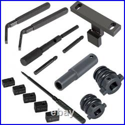
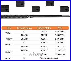
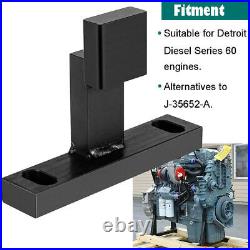
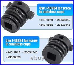
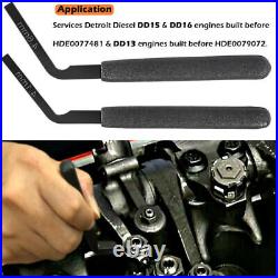
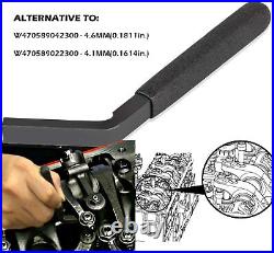
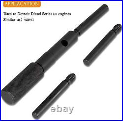
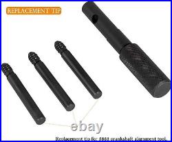
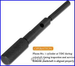
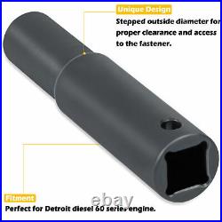
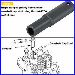
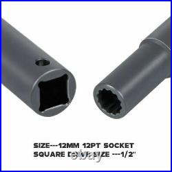

Valve Tool Set Injector Cam Gear Retaining Socket for Detroit Diesel 60 Series. Included Crankshaft alignment, Cam gear holder, 12MM 12PT 1/2 inch Rocker Arm Shaft Socket, Injector cup remover and installer and Injector height gauge. Made of high quality steel and finish. Make valve service job easy and correct, such as remove and install injector cup, rocker arm and cam device fixing bolt. Tool set for Detroit Diesel 60 Series. Crankshaft alignment pin is used to ensure proper crankshaft alignment, equivalent to j-45947, fit for detroit diesel 60 series. Cam gear holding tool used to correctly keep the cam device fixed without damage while removing/installing the cam device fixing bolt, alternatives to j-35652-a, fit for detroit diesel 60 series. 12MM 12PT 1/2 inch drive extra deep socket used to torque the rocker arm nut to oe specification and has a stepped outside diameter for proper clearance and access to the fastener, fit for detroit diesel 60 series. 4.6mm 4.1mm jake brake feeler gauge for checking the valve clearance, allow easier insertion between slave pistons contact surface with the exhaust valve adjusting screw. Fit for dd15 & dd16 engines. Injector cup removal installation tool used for screw-in stainless cups to easily and promptly remove or install, fit for detroit diesel 60 series. Injector height gauge kit properly set injector body height to the injector follower for proper fuel injector timing, fit for Detroit Series 50 and Series 60 engines. 4.1+4.6 MM Engine Brake Tools Adjustment Steps. 1 Set the lash on all the exhaust adjusting screws first (all the adjusting screws in direct contact with the exhaust valves). 2 Rotate the engine until a given cylinder is at maximum intake lift. When this is reached, the brake lash can be set on this cylinder. 3 When the engine brake rocker arm is in contact with the exhaust valve, set the lash between the engine brake rocker arm adjusting screw and the actuator piston stem. DD15 & DD16 engines built before HDE0077481 use Engine Brake Adjustment tool W470589022300; set the lash to 4.1 mm 0.1614 in. DD13 engines built before HDE0079072 use Engine Brake Adjustment Tool W470589022300; set the lash to 4.1 mm 0.1614 in. 4 Lash the engine brakes in the following firing order: 1, 5, 3, 6, 2, and 4. 5 Torque the locknut valve adjusting screw to 50 N·m (37 lb·ft). Install the rocker cover. How to Use:(Gear Retaining Tool). Insert the shoe of the camshaft drive gear torque holding tool J-35652-A, through a lightening hole of the camshaft drive gear. Using the 3/4 in. Square hole in the center of the crankshaft pulley, bar the engine over slightly so that the bolt holes in the holding tool align with the access cover bolt holes in the gear case cover. Install the camshaft drive gear torque holding tool J-35652-A to the gear case, engaging one of the lightening holes in the camshaft drive gear. Use two of the access cover bolts to secure the tool to the gear case cover. Using a long 3/4 in. Drive breaker bar and a 27 mm impact socket, remove the camshaft drive gear mounting bolt. Remove camshaft drive gear torque holding tool J-35652-A from the gear case cover. Insert a clean shop towel into the gear case opening to prevent removed bolts from falling in to the gear case. Notic: Do not allow bolts or the shop towel to fall into the gear case. Failure to remove loose bolts or the shop towel from the gearcase may result in severe gear train damage at engine startup. Remove the three (current) or two (former) camshaft thrust plate mounting bolts carefully to avoid dropping them into the gear case. Removing and installing EPA07. Drain Engine Coolant before removing injector tube. Injector tubes may be damaged if excessive force is used during removal. Install injector cup removal/installation tool into injector bore. See pictures for correct tool. Aligning tool with slots in tube. Turn injector cup removal/installation tool and injector tube counter clockwise to remove. Check injector tube for cracks or defects. Paying careful attention not to score cylinder head to injector tube sealing surface, clean injector tube threads with fine wire brush. Pay strict attention to keep debris out of fuel supply line. For cleaning injector tube interior sealing surface, a chemical solvent may be used. Thoroughly clean injector bore, install new O’Ring with a silicone based lubricant into injector tube groove. Use high temperature nickel based antiseize lubricant to coat injector tube threads. Install injector tube on injector cup removal/installation tool. Using injector cup removal /installation tool install injector tube in injector bore. Tighten injector tube to torque specs. Please refer to owners manual. 26-33 ftlb loosen 180 degrees tighten 26-33 ftlb. Tip of the injector must be flush with the fire deck or sunk into the cylinder head. Ensure tube does not protrude past fire deck into cylinder. Re-install or replace shim. Ensure NEW shim is of same thickness as original one. To insure proper tube depth after fire deck has been milled a shim is used between tube and cylinder head in remanufactured cylinder heads. Note: Please refer to your service manual for most up to date procedure. Please list your special requests color, packages, etc. We maintain high standards of excellence. Feedback is very important to us. Pls contact me first before you leave Neutral. I will do my best to solve the problem, thanks! This item is in the category “eBay Motors\Automotive Tools & Supplies\Hand Tools\Hand Tool Parts & Accessories”. The seller is “chenzj2020″ and is located in this country: US. This item can be shipped to United States.
- Brand: CHZJ
- Warranty: 2 Year
- Type: Valve Tool Set

